"Making of Mouses" by Michael Little
Splines or wires as they are called in EIM, are a fundamental part of the construction process. In the shot above you can see where I have constructed a simple cylinder which is the main body of the mouse. Using the knife tool allows me to cut through solids, surfaces and other wires with ease. Just make sure that you are in the correct viewport when you use the tool. When I cut the main cylinder for instance the front viewport was active. Select the object you want cut and then the wire, double click and viola, you’re done. Here I have done the cutting and have used the scale tool to reduce the size of the center piece to give a base for the scroll wheel. Then beveled the top and bottom edges of the main cylinder where they hold the wheel base.


Now that we have the base for the wheel we can either make a new cylinder the correct size to fit on it or duplicate (Command or Control D) the base and scale it up to the correct size. Once this is done you are ready to construct the vertical ridges on the edge of the wheel. For this we will use the misleadingly named Linear Copies tool. As you can see our basic wheel cylinder is constructed so that it falls exactly on the center of our grid Y = 0. (We are working in the top view). This is important because if it isn’t then the tool won’t work properly. I have constructed a smaller cylinder, longer than the base wheel cylinder and, moved it so that it intersects. In the Linear Copies dialog box – double clicking on the icon brings it up – I have estimated that 36 of the smaller cylinders are needed around the perimeter to give the effect I need. So, enter 36 in No. of Copies. Since we want the copies to go all the way round the outside edge of the base wheel, divide 360 by 36 which will give the degree of separation between each copy. Plonk that number (it’s a no brainer 10) into the Rotation Angle box and that’s it, we can leave the rest at their default zero settings. The only other thing to remember is to set Rotate About to Y because we’re working in the Y viewport.

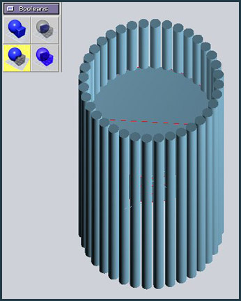
Here is the result of the tool shown in the top and perspective views. Select all the newly created cylinders – except the original! The copy tool is not very smart and puts a duplicate right on top of your original which is not visually obvious. If you just select them all and then use the join tool which is the next step, you will get an error later on and be left scratching your head and wondering what’s wrong. The join tool is useful because it connects objects which are not actually touching each other. In this case by joining the cylinders now we can perform one boolean subtract operation in the next stage instead of 36 separate ones.
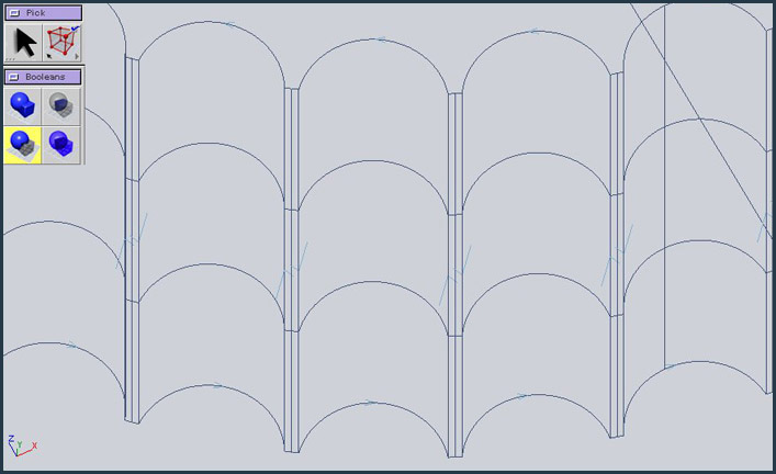

Above left shows the result after the boolean subtract operation. I wanted the scroll wheel to appear to be made of a softer rubberized
material with soft edges, so the next step is to use the round bevel tool on the booleaned wheel. Above right you can see where I did a
test on two of the side edges to see what the right radius would be for the bevel. A couple of things you need to be aware of here. One
is that the pick tool has to be at the correct setting. In this case, because I wanted to get the radius right I need to set it to edge. You
can see this displayed in the Pick icon box. This is something that can trip you up really easily so beware. The next thing is that you
can change the bevel radius by holding the E key down and clicking on the bevel circle and dragging. The bevel radius will increase
interactively if you drag to the right and decrease on the left drag.

Making of Mouses
Popular Tutorials
-
 Free set of photo references for our members
Posted on Nov 15, 2010
Free set of photo references for our members
Posted on Nov 15, 2010
-
 Photo References
Posted on Oct 6, 2010
Photo References
Posted on Oct 6, 2010
-
 Modeling Competition
Posted on Dec 10, 2010
Modeling Competition
Posted on Dec 10, 2010
-
 Modeling a High Definition Building – part 1
Posted on Dec 9, 2010
Modeling a High Definition Building – part 1
Posted on Dec 9, 2010
-
 FREE photo reference sets for you – only for registered members
Posted on Oct 2, 2011
FREE photo reference sets for you – only for registered members
Posted on Oct 2, 2011
Try something new

Latest Comments