“Making of Glimpse ” by Toni Bratincevic
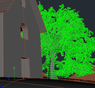
Trees are very easy to create in maya, thanks to paint effects. But, if you use the mental ray then you have to transform it to the mesh object. For example for the tree next to the building, I’ve picked one paint effect preset, and painted the tree, which I modified to fit my needs. Then I’ve converted it to the mesh using Convert PE to Polygons option. The first time when I did the conversion, maya created too much polygons. So to lower down the number of polys, before I’ve done the conversion I went to the Attribute editor of paint effect stroke and lowered the value for Tube sections and Sub Segments in the Mesh section. If you have situation where you need to get close to the tree, then it would be probably better to increase the mesh complexity of the tree, or leave it as it is if that is enough..
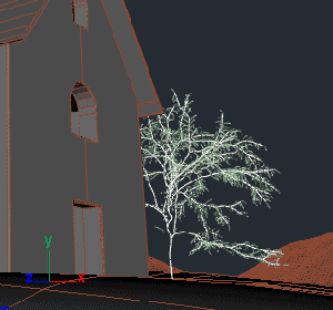
The painted tree using one of PE presets.
Used tools:Paint Effects > Get Brush+ Modifying attributes of the painted tree
After the right tree setup I converted the tree to the mesh.
Used tools:Modify > Convert > PE To Polygons
These are the basic steps I’ve made when modeling. I’ve added a lot of other details lately using boolean tools, cut, split and move polygon points tool. Let’s see few techniques I’ve used in texturing part.
3. TEXTURING
This is one of the most interesting steps in the image creation process. You can have the model that is accurate and detailed but if it doesn’t have the right textures and lighting it can look totally flat and uninteresting to the viewer. There are two ways to do the texturing. You can do it with procedural textures or with image maps.
The first method will give you more computer generated look, but it will use a small amount of memory. The procedural textures are calculated using the mathematical algorithms behind it. They can be divided in two categories, the 2D procedural textures and 3D procedural textures. To map the 2D proced. on polygonal objects you will need to set the right UV maps, or you can project it on model. On the other hand if you are using the 3D procedurals, since their calculations are dependent on the 3d point in space, you don’t need to create UV maps.
The second method of texturing by using image textures will give you very realistic appearance of materials, but it will use more memory. Of course you need to have the texture collection, or you can photograph textures by yourself. If you decide to use the texture collections, one of the best choices will be to purchase one on internet, like the 3DTotal Textures CD that I’ve used in my image. For now there are 3CDs with 3DTotal textures with the collection of color and bump maps. The textures from that CD’s are also seamless, that means that you will not see any seams when they are repeated over the surface.
When texturing the polygons with image maps, first thing you have to do is to define the UV mapping of the objects. For this kind of objects, like building, defining UV mapping is not too difficult to do. This will be shown in next few steps… as an example I will use the main building part.
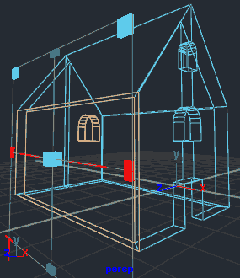
As you can see from the first picture below, the initial UV map, after I’ve finished the modeling part, was not what I wanted. This is surely not something intuitive on which you can paint the textures on in photoshop. But, there are tools to do UV unwrap, so let’s use it. I’ve made one decision when I came to process of UV mapping of this building, and that was that I will define the UV map for only two walls that are pointing towards the camera, since other walls are hidden from the viewer. As you can see that is, when looking from front, the left wall with window in it, and front wall with door and windows. Don’t worry about the top part where roof stands, it will be covered with the roof object. So, to create the UV maps of these surfaces I have selected them (select faces) and then set the planar mapping on them. These two examples (pic2 and pic3) show just that. I’ve selected the faces for the side wall, went to options of Planar Mapping, turned on the Fit to Bounding Box, selected the mapping direction which have to be perpendicular to the faces, and that was it. This was also done for front wall. One more thing, If you try to do the selection for the front or side wall, don’t forget to select the faces of the door and windows.
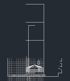
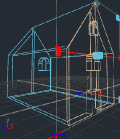
Initial UVs after the modeling process… very very bad, I need to fix this. 😉
Used tools:Just switched to UV view to see this mess….
Selected the faces from side wall and created Planar Mapping.
Used tools:Edit Polygons > Texture > Planar Mapping
Also for the faces at front wall, created Planar Mapping.
Used tools:Edit Polygons > Texture > Planar Mapping
Now the next step. The UV map at this stage is still not finished. What I did in the steps above is that I got the usable proportions (or projections) of the front and side wall, so when I paint the textures on them, they won’t be distorted. But, the projections are overlapping as you can see in the first picture below. This must be fixed. There are also the other leftbehinds of the other polygons for which I didn’t define the mapping, but I didn’t bothered with them because they will not be visible in final picture. What I’ve done now was that I’ve put side by side the UVs for front and side wall. It is possible to do this by hand, but it is also possible to get a little help of layout tool. I did it with the layout option for which I set the Along U and Uniform Scale attributes. After I’ve clicked on Apply, what it did was that it layout the UVs like in second picture. The next step I’ve made was that I moved UVs for front and side wall from the top right area of UV grid to the bottom area and scaled them to fit the area from 0 to 1 in UV space (pic 3). At the end I selected unwanted UVs for other walls and moved the apart from the top right side of the UV grid, and then I moved wanted (front and side walls) UVs to the top right quarter in the UVs grid.
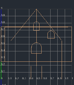
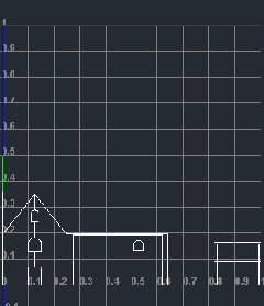
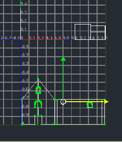
The UV of two walls after the projections. This should be placed next to each other.
Used tools:Only switch to UV window.
UVs after the layout tool was used. I would only use the first two parts on the left.
Used tools:in UV Editor > Polygons > Layout UVs
The UVs of two important parts were selected, moved to the bottom, scaled, and after this moved to the top.
Used tools in UV editor>first I selected one UV point of the the front and side wall and then :Select > Select Shell + Move and Scale tools


Latest Comments