STEP BY STEP NOSE BOX MODELING by JY
Hello friends! 🙂 We are going to model nose with use of box modeling technique in 3D studio Max 7. This is very detailed tutorial so in case you are just starting with box modeling or 3d MAX you have found the right place! 🙂 Let’s start with reference. It’s a always a good idea to have some reference before you start with actual modeling process. This way you can save lot of remodeling and the result is always much better compared to “guess modeling”. To see the end result you can download the finished model.
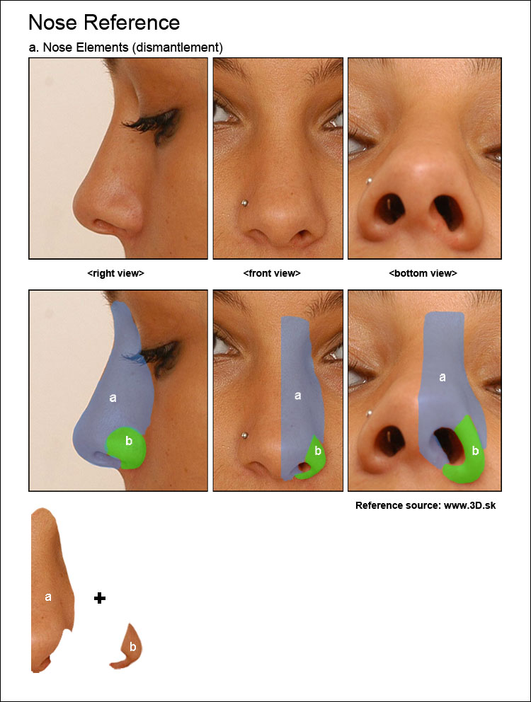
Reference:
I have found good reference photos on www.3d.sk. It has more than 29.000 hi res photos. Unbelievable! 🙂 It’s not for free but I feel like they are selling it for nothing. There is also lot of free samples, so be sure to check it out.
Ok, I am not going to use these photos as an viewport background this time as we need just the general shape. Notice the 2 main parts of the nose, lets call it “a” and “b”. Its also a good idea to keep your reference near so you can always check it out during modeling process.
Modeling:
OK :), open your 3D studio max. First of all setup the viewport as on the picture above. To change the viewport right-click it’s name (for example Front) and choose Views/……. (in this case Right). When finished create basic plane object in the front viewport (Use right top “create” tab) with 2 Width and 2 Length segments. To move between viewports just right click in to the viewport you are going to work in.
To learn more about basic viewport navigation choose: help/tutorials/Getting Started with 3ds max/Animated Still Life/Navigating a Scene. (you can find help menu in the right top part of your 3ds max toolbar)
Right click the plane and chose Convert to: > Convert to Editable Poly. (to change the object shading and edge display in your viewport try diferent combinations of F3 and F4 keys on your keyboard)

Choose vertex selection (you can use “1” shortcut) and select the left column of vertices.
Delete the selected vertices so we can work only on the right side of the nose and mirror the left side.
Now select the object (switch to object mode by using “6” shortcut) choose the “mirror button” from the top toolbar and check Mirror Axis: X, Clone Selection: Instance.
Use “6” shortcut for “top level” selection and select the original plane on the right side. Use “1” again for vertex selection. Please remember that if you are working on sublevel (vertex, polygon, face..) and you want to select another object in the scene, you have to switch to “top level” first.
Ok , now the real fun begins. Select the right column of vertices and scale it down in Y axis in front viewport. To access scale command either right click on the object and choose “scale” o press “r” key. You can access other command similarly. Please try it: “q” for select, “w” for move, “e” for rotate and “r” for scale. You can add vertex to existing selection by holding Ctrl during selection or subtract vertex from selection by holding Alt during selection. Practice it a little so you are familiar with these shortcuts, now use Ctrl-z in case you have moved something you didn’t wanted 🙂
You have already scaled down the right column of vertices in Y axis, right? Now keep the right column of vertices selected and move it to the right in right viewport. Next step is to select center row of vertices and move it to the left so you end up with the shape on the above picture. Check it out in all viewports to make sure everything is right.
Select the right Edges in front viewport. (use “2” keybord key to activate edge selection. Similarly “1” for vertices, “3” for border, “4” for polygons, “5” for elements and “6” for top level selection. Practice it so you become familiar with it.)
With edges selected hold down the SHIFT button on your keyboard and move the vertices to the right. This way you will extrude the edge. This technique will be our main building method. Its very fast and it’s also fun :). Scale the edges and/or vertices so they match the above picture.
With selected edges extrude again (move while holding the SHIFT down) )and repeat the whole process to match the picture above.
Extrude edges in Right viewport, move and scale edges and vertices so they match the image.
Now extrude edges in right viewport again and move and scale edges and vertices so they match the image.
Select top 2 edges.
Extrude, move and scale..
Use “1” shortcut for selecting vertices. Position the right vertex of the extruded edge so it match the vertex on the right (that is part of the nostril) Now select both, right click and choose weld.

This should weld both vertices. In case it doesnt work repeat the proces but choose the square buton on the left side of weld command. Increase the “Weld Threshold” and click OK. (You can see the result in real time as you click and drag the left mose button up and down on the arrow icon on the right side of the Weld Threshold field.)

Select the bottom edge.

Extrude the edge and reposition vertices..
Extrude the edge in right viewport and reposition vertices..
Extrude the edge and reposition vertices..
Now select the nostril edges according to the picture. Continue on next page :).
Nose Box Modeling
Popular Tutorials
-
 Free set of photo references for our members
Posted on Nov 15, 2010
Free set of photo references for our members
Posted on Nov 15, 2010
-
 Photo References
Posted on Oct 6, 2010
Photo References
Posted on Oct 6, 2010
-
 Modeling Competition
Posted on Dec 10, 2010
Modeling Competition
Posted on Dec 10, 2010
-
 Modeling a High Definition Building – part 1
Posted on Dec 9, 2010
Modeling a High Definition Building – part 1
Posted on Dec 9, 2010
-
 FREE photo reference sets for you – only for registered members
Posted on Oct 2, 2011
FREE photo reference sets for you – only for registered members
Posted on Oct 2, 2011
Try something new

Latest Comments