“Realistic lighting with LDRI images” by Toni Bratincevic
Open the hypershade window Windows > Rendering Editors > Hypershade, or you could open the hypershade window in one of your viewports Panels > Panel > Hypershade. Now that you have opened the hshade, select the half of the sphere around scene and in hypershade windows select Graph > Graph Materials on Selected Objects. When you do this in the Work Area of the hypershade window the shading network will apear as in next picture:
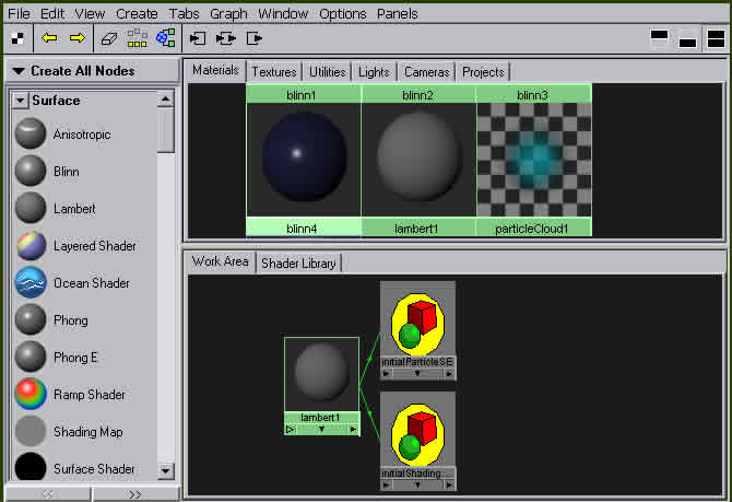
This means that initial lambert1 shader is attached to the sphere. Since we don’t want this, we will create new surface shader to serve our big half-sphere. So what surface shader should we use? This time we will choose the Surface Shader since we don’t need the lambert or blinn shaders because the material of our half sphere doesn’t need to react with the light. Yes, I have used the Lambert shader in my first global illumination tutorial, but I have learned a few other things since then. 😉 But, before you create Surface Shader, increase the space for Work Area, go to the Tabs > Show Bottom Tabs Only, and also clear the Work Area by clicking on Graph > Clear Graph. We will leave the tab on the left where nodes are since we have to use them very often.
Ok, for our first step, with your middle mouse button from the bar on left pull the Surface Shader in your Work Area. Now we have to attach this shader to our sphere so select the sphere and the right click (and hold) on the surfaceShader (hypershade Work Area) and select Assign Material To Selection. This will attach our shader to the sphere. You can check if it is attached to the sphere by clicking on the sphere and then in Hypershade select Graph > Graph Materials on Selected Objects. If the surfaceShader material appears in the Work Area of hypershade, then you have done it correctly.
Let’s explain a little bit how does surface shader with half-sphere affect the scene. By default surface shader produces the black color of the surface on which it is attached to. If you render the scene at this moment you’ll get the black picture. But, you can easily change this by changing output color of the surface shader. To do this double click on the surface shader icon in the work area of the hypershade, or click one time on it and press Ctrl+A. This will bring the new window on your screen named Attribute Editor: Surface Shader. Now in the Surface Shader Attributes move the slider of the Out Color to the right, somewhere in to the middle. Chose MentalRay as default renderer and render the scene. After the renderer has done its job the shaded scene appears in the render view. It should look like this:

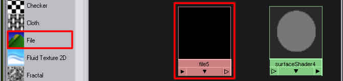
Yes, we created illumination of the scene but it is sooo boooring. 😉 So let’s go and attach the image of the sun to surface shader color Out Color. First, from the nodes menu on the left with your middle mouse button click and drop the File node (small red rectangle) in to the working area . The file node appears in the work area (marked with the big red rectangle)
After you have done this you must connect the file node to the surface shader. To do this press and hold CTRL and with your middle mouse button click – hold on the file node and drop it to the surface Shader node. If you did it right, the green line should appear between these two nodes, and if you point your mouse over the green line it should say what attribute of the file node is connected to the surface Shader, just like in this picture:
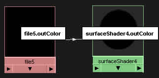
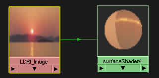
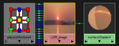
As you can see green line connects the output color from the file node to the out color of the surface Shader. Since the file node doesn’t have any file attached to it, it produces black color. To change this double click on the file node. The attribute editor of the file will pop up. Let’s just rename it to get more organization in our shading network… on the top of the attribute editor where the “file:” is, type the name “LDRI Image”. Now in the File Attributes section at in the Image Name attribute press on the little folder icon and select our image. The shading network in the work area of the hypershade should look like this:
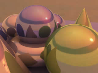
Now do one quick test render. Wow, that looks much much better than before. But, there is one small problem, the image is not mapped correctly on to the sphere. To correct this, select the surface Shader node in the work area and click on the Graph > Input Connections. The new node will appear in the work area which is connected to the LDRI_Image node, and is named something like place2DTexture, just like in picture:
Double click on the place2DTexture to bring up it’s Attribute Editor. After it opens, change the Rotate Frame parameter to the 90. This will rotate the mapped image for 90 degrees and it should correct the problem. We will do one test render to see if it is corrected now.
Realistic lighting with LDRI images
Popular Tutorials
-
 Free set of photo references for our members
Posted on Nov 15, 2010
Free set of photo references for our members
Posted on Nov 15, 2010
-
 Photo References
Posted on Oct 6, 2010
Photo References
Posted on Oct 6, 2010
-
 Modeling Competition
Posted on Dec 10, 2010
Modeling Competition
Posted on Dec 10, 2010
-
 Modeling a High Definition Building – part 1
Posted on Dec 9, 2010
Modeling a High Definition Building – part 1
Posted on Dec 9, 2010
-
 FREE photo reference sets for you – only for registered members
Posted on Oct 2, 2011
FREE photo reference sets for you – only for registered members
Posted on Oct 2, 2011
Try something new

Latest Comments