“Head modelling ” by Glen Southern
INTRODUCTION TO ZBRUSH To me, Pixologics Zbrush lives in a world somewhere between 2D and 3D never really knowing which camp to lie in. With it I can create 3D meshes that can be textured and have native materials added to them. Zbrush uses a technology called `Pixols` that sees each pixel as a 3D image that retains width, height and, more importantly, depth information. Once you `snapshot` a model (or Ztool) into an image you can still add depth with a number of brushes, change the model’s material and even adjust the lighting. In this tutorial I will attempt to walk you through the creation of a detailed head study (called `EFXterminator`). The steps will lead you through modelling the head from a basic 3D sphere, adding colour and material to the model then creating and adding textured eyeballs. Finally, we’ll model the hoses and metal parts of the image before moving on to lighting and rendering. The steps I describe are not the only way to achieve things in Zbrush.It is such a versatile program that you can find a multitude of ways to do the same job. I used Zbrush 1.2 to create this image with a document sized at 2500×2500 with three layers. It is possible to re-create this image using the demo version. However, some of the settings and sizes may vary. I use a 1 gig AMD-based PC with 512mb of RAM and Win98. MODELLING BASICS

figure 1.
To start off this modelling session you need to understand a little bit about the TRANSFORM panel. (See figure 1.) The following steps apply to any 3D object or primitive that you can select from the TOOL panel. To model an object you need to place it into the document window. To do this, with the tool (model) selected, click into the window and drag out an object. To move, scale or rotate the object you can use the panel or press key `W`, `E` or `R` respectively. When pressing any of these keys a multi coloured `gyroscope` appears. Try each of the modes to get used to using the gyro to get the desired result. TIP: To `move` along an axis, pull the coloured end of the gyro. To `scale`, click inside the gyro and drag up or down. To rotate, click inside the gyro and drag in the desired direction To model or shape the object into the desired shape you need to enter the EDIT mode, press `T or use the transform panel (Figure 1.) When in the EDIT mode the cursor turns to a red dot with a ring surrounding it. The red dot is where your changes will be made on the object as you model. To rotate the model in this mode click while holding the cursor away from the object and drag up or down. Different effects can be achieved using the transform panel by clicking `draw pointer` (add depth to the object or remove it by holding down ALT), `move` (pull or push an area of the object) and `scale` (increase or decrease in size an area or polygons). (See figure 3.) To enlarge the `area of effect` on the object go to the DRAW panel and adjust the `DRAW SIZE` slider up or down. You will notice that the red ring grows or shrinks helping you to judge the size. In the DRAW panel you will also find `RBG Intensity` and `Z Intensity` which affect the amount of colour and depth applied to the object as you model. At some stage you may need to turn `colour` or `Z` (depth) off. This is done by selecting or deselecting the correct box (green is selected, grey isn’t). These steps are the basics of constructing any 3D organic model in Zbrush. TIP: The best results are achieved by keeping the `Z Intensity low when adding depth or pulling a portion of the model. This will let you subtly adjust the shape stage by stage using the different tools. Now is a good time to tell you about `snapshotting`. A model (Or ZTOOL) in Zbrush is `live and editable` in the document window until you `snapshot it into the image (Press CTRL+S or the `camera` Icon shown in the transform panel in Figure 1.). Once you `snapshot` a copy it is no longer editable and cannot be moved or rotated. It does, however retain its depth information and can be modified with some of the 2D tools (Simple Brush, Blur Brush etc.) The original ZTOOL remains in the TOOL panel and can be saved as a .ZTL (Native format) or exported as an .OBJ or a .DXF Losing the facility to modify 3D objects was one of the first hurdles I came across in Zbrush. It is such a departure from the norm that it takes a while to feel comfortable with it, when you do, it becomes second nature and going back to being able to rotate a wireframe whenever you like seems weird.
MODELLING THE HEAD
Start Zbrush. Go to the DOCUMENT>MODIFIERS panel (usually on the left) and adjust the document size to Height 2500, Width 2500 (if you have the demo you will be limited to 640×480). Select `PRO` to allow you to adjust the proportions. To begin modelling go to the TOOL panel and select the Sphere3D tool. Click TOOLS>MODIFIERS>INITIALIZE and change `Hdivide` to 512 and `Vdivide` to 256. This will give us the maximum possible subdivision count for this object (lots of polygons).

figure 2.
Start Zbrush. Go to the DOCUMENT>MODIFIERS panel (usually on the left) and adjust the document size to Height 2500, Width 2500 (if you have the demo you will be limited to 640×480). Select `PRO` to allow you to adjust the proportions. To begin modelling go to the TOOL panel and select the Sphere3D tool. Click TOOLS>MODIFIERS>INITIALIZE and change `Hdivide` to 512 and `Vdivide` to 256. This will give us the maximum possible subdivision count for this object (lots of polygons). Click in the document window and drag out a sphere leaving plenty of space around it. As we are only modelling the head at this stage the position doesn’t actually matter. At this stage we want to go straight into `EDIT` mode so press `T` on the keyboard and a red dot/ring will appear. Because the head we will be modelling is fairly symmetrical we need to turn on `symmetry`.Go to TOOL>MODIFIERS>DEFORMATIONS>SYMMETRY and select `X`. You will now have two dots on the model. Any change made to one side of the model is exactly duplicated on the other side saving you a lot of work. Figure 2. To begin the modelling you will need to `pull` the Sphere into the basic head shape. Select `Move` (W) and pull the bottom of the sphere down. If the effect is too dramatic you can CTRL+`Z` to undo. This is a good time to adjust the `DRAW` size to get the right effect for this part of the modelling. Click-Hold away from the head and rotate it slightly. Pull out a neck, back of head, chin and a forehead. (See figure 2. Heads 1 and 2) To add features to this cone-head we need to switch to the `DRAW PONTER` (`Q`). Rotate the head so that it faces you and `paint` depth onto the face. Build up the forehead, the nose, cheeks, lips and ear bumps. Add a bump for each eye for now. To indent the model, still in the same mode, hold down ALT and paint. Indent the cheek recesses, nostrils and the eyeholes. Remember, you may need to reduce the `Z Intensity` in the DRAW panel to make subtle adjustments. Try to follow the steps in Figure 2. Keep rotating and adjusting until you get the desired effect. (See figure 2. Heads 3-8). Add features like frown wrinkles and bags under the eyes. If you need to move the head on the canvas you can exit `EDIT` mode by pressing `T` again. The gyro appears and you can select `MOVE` by pressing `W`. Pull the gyro (grab the coloured ends) and move it in the direction you want. To continue modelling, press `T` and re-enter `EDIT` mode.To model the ears you can use `SCALE` (E) to enlarge the ear area. Use `DRAW POINTER` to shape the lobe and make an indentation then use `SCALE` (E) to reduce the ear back down to the correct size. This will take some practice as it is not easy the first few times you try it. Make sure you model the `bumps` in the head where the metal hoses will fit. NOTE: If you select another tool by mistake at this point you will `snapshot` your head into the document – common frustrating mistake. If this happens CTRL+`N` clears the entire layer and you will notice a copy of your head is left in the `TOOL` panel. You can re-select it and `draw` it back into the document and continue to edit it. ADDING SOME COLOUR AND MATERIAL

figure 3.
Later we will be changing the material that is applied to the head. For now we want to add some colour. With the head still in `EDIT` mode go to the TOOL panel and select TOOL>MODIFIERS>TEXTURE and select COLORIZE. This will flood the model with the currently selected colour (you may not see a difference). To add colour without adding depth turn off `Z` in the draw panel (un-select all buttons). Finally ensure that you have `DRAW POINTER` selected (Q). Go to the COLOR panel (on the other side of the screen usually) and pick a light cream colour to start painting onto the head. Begin painting as you did the modelling but notice that only colour is added, no depth because `Z` is switched off. Paint the whole head, adjusting draw size as needed. (The quickest way to achieve this is to flood fill the head from the COLOR panel but it’s good to practice) Change to a slightly darker colour and begin to shade darker areas in the eye sockets, wrinkles under the chin etc. Keep doing this until you are happy with the effect. Figure 3. TIP: You can reduce the amount of colour added by reducing the `RBG intensity` slider in the DRAW panel. The effect is like a semi-transparent airbrush. To add or change the material that is used you will need to enter the MATERIAL panel on the left side of the screen. With your `head` still in `EDIT` mode, select `BasicMaterial` from the options available in the material palette. If it is not there click the top of the panel and a full range of materials will be shown. It would be possible to write a whole tutorial on materials so I will just give you the parameters to input. With `BasicMaterial` highlighted go to MODIFIERS and adjust the following: Ambient=10, Specularity=4, Noise=0.427, Noise Radius=24. As you have the head still `live` in `EDIT` mode in the document window all the changes will update automatically. Now save the material, MATERIAL>MODIFIERS>SAVE. We will need this later.
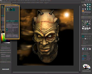
figure 4.
SETTING THE SCENEWhen you are finished colouring the head you can position it in the document in its final position. Zoom out (minus key, plus to zoom in, 0 to reset to 100%) until you can see the whole canvas on screen. Exit `EDIT` mode and the gyro will re-appear. Select `SCALE` (E) and enlarge the head to fill the canvas by clicking inside the gyro and pulling away. Get the size correct then change to `ROTATE` (R) and use the gyro to position the head at the correct angle for the final image (See Figure 5.) Now use CTRL+`S` to snapshot the head into your image. TIP: It would be a good idea to go to the TOOL panel and save the head as a ZTOOL for future use. If you close Zbrush without saving the ZTOOL you will lose it even if you save the document. The head is now in place and sitting on its own layer. We need to add two more layers, one for the background and one for the eyes and metal hoses. Go to LAYERS>INVENTORY>CREATE and do it twice to create two more layers. You can see them in the LAYER panel. The `green ` coloured layer icon is the current active layer (It should be the one with your head on it). Click into one of the new layers. This layer can be used to import a bitmap image (either .BMP or .PSD) as a background. For this project I created a 2500×2500-blurred image with the same colours as the head. You can leave it blank for now and create an image to import later. When you import the image, if it isn’t the same size as your document, it will be stretched to fit. Click onto the other new layer and this is where we will create the eyeballs. CREATING THE EYES

figure 5.
Select a Sphere3D from the TOOL panel. Click anywhere in the document window and drag-out a sphere. As you are on a different layer to the `head` you will not affect it. Go to EDIT mode by pressing `T`. Open MODIFIERS>INITIALIZE submenu. Set the mesh resolution to Hdivid=256, Vdivid=128. Go to TOOL>MODIFIERS>TEXTURE and select COLORIZE. The sphere will turn pure white (if it’s not already). Go to TOOL>MODIFIERS>SYMMETRY and check `Z` then `R` for RADIAL SYMMETRY. Set the radial slider to 30. This should now give you a ring of red dots around the eyeball. We only want to colour the eyeball and not effect the surface with depth. Go to the DRAW panel and click the green coloured ZADD button to de-select it. Now go to the `COLOR` panel on the other side of the screen and select a black colour. Bring the dots on the eyeball together and begin to draw a pupil. You can get different effect by changing the `NOISE` slider/curve in the TRANSFORM>MODIFIERS panel. If you find too much colour is being added go to the `DRAW` panel and adjust the ‘DRAW SIZE’ and ‘RBG intensity’ sliders. When you have finished the pupil select another, lighter colour for the iris (I used a couple of shades of orange) and draw the outer ring. Follow this with a thin line of black around the iris and then finish the eyeball with a cream colour. At this point you can choose a material for the eyes. To simulate a glossy wet appearance I chose the default `Toy plastic` from the MATERIAL palette. It will update as soon as you select it. Now we need to place them into the document. Exit edit mode (`T`), use the gyro to scale, move and rotate the eye into position over the socket area. TIP: This is where you realise that the document has retained depth. With the eye in `move` (`W`) mode you can move it along the `Z` axis (in and out of the image) by simply clicking outside the gyro and dragging your mouse up (in) or down (out). Get the eye into position in the socket and `snapshot` a copy into the image with CTRL+`S`. Snapshot leaves the eye live and `stamps` a copy so you can continue to move the eye. Using `W` and the gyro, slide the eye across to the other socket and position in the same way as the first. As the eyes are on a separate layer we can `paint` on them without affecting anything else. Pick the `SimpleBrush` from the tool menu. Pick a near-black colour from the Colour Panel. In the draw panel set the RGB Intensity to about 7 (near transparent) and turn `Z` off. Paint a dark shadow across the top of the eyeballs and around the edges. You can use the ALPHA panel to try out some of the other Alpha Brushes to add veins using a red colour.
 figure 6.
DETAILING THE SKINSwitch layers back to the `head` layer. To get the shiny effect on the lips select a new material (any) from the MATERIAL panel. Go to MATERIAL>MODIFIERS>LOAD and load the pre-saved basic material into the new slot (overwriting the material you just chose). Increase the settings for Specularity, Noise and Noise radius (small amounts). Using the `SimpleBrush` with `Z` off paint the new material onto the lips. If the settings don’t look right adjust then REMEMBER: All materials in Zbrush remain `live` and can be adjusted throughout the creation of the image. You will need to change the colour in the COLOR panel and keep the `RGB Intensity` low (high colour transparency) Unlike other 3D applications that use displacement and bump maps, the detail on this model was added with ALPHA brushes or painted on with the Simple Brush. To `paint` the veins and cracks use the `SimpleBrush` with different alpha brushes. The `DRAW` panel can be set to `ZCUT`, which will then use the ALPHA brush to add cracks and creases. You can also make your own in a paint package and import them into the ALPHA panel. Remember you can also change the colour setting as you go. The stitch areas were `painted` on with `Z` turned to `ZCUT` and a red colour. Надоело порно и хочется найти видео, где есть эротика? Ретро? Вот здесь ретро эротика и просто кладезь интересных роликов в самых разных жанрах.
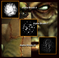 figure 7.
3Dtutorials.sk recommendation:
To maximise the realism of your 3D characters we recommend to use high quality human photo textures from the #1 texture website www.3D.sk
ADDING THE HOSEBefore creating the hose you need to make an alpha map in a bitmap painting package. It needs to be approximately 500 wide by 80 high and be black and white repeats (i.e. like a pedestrian crossing). It needs to be a .BMP or a .PSD for Zbrush to recognise it. In Zbrush go to the TOOL panel and select Ring3D. Go to TOOL>MODIFIERS>INITIALIZE and change Coverage=230, Hdivide=128, Vdivide=128. Import the black and white bitmap into the ALPHA panel. Go to TOOL>SELECTION>ALP which then grabs the Alpha brush and applies it as a mask to the ZTOOL. Now use TOOL>DEFORMATIONS>INFLATE to create the Hose shape. The black areas of the bitmap are used as a mask, inflating only the White areas. Make sure you change layers to the eyeball layer. With the hose/ring selected in the TOOL panel draw/drag it into the document window. Enter `EDIT` mode (`T`) and apply one of the `Metal` materials and use a dark grey colour. Exit `EDIT` mode (`T`) and use the gyro to position the hose. Remember `W` in+out. Snapshot the hose into position and move the hose to the next position using move and rotate. Repeat until all hoses are placed. LIGHTS AND RENDERINGThe last stage is adding some lights and rendering the image. In the LIGHT panel two lights are set to `on` as default. These are both `SUNS`. Click one of the light slots that isn’t highlighted and it should turn `green ` (on). Click into the `COLOR` panel and pick an orange colour. Click under the LIGHT panel in the colour box and that should change to orange. In LIGHT>MODIFIERS>TYPE choose `GLOW`. In LIGHT>MODIFIERS>PLACEMENT drag the `PLACEMENT` button to the document window to where you want the `glow` to appear. These settings will only be shown when you use `BEST RENDER` in the render panel. You will want to try different settings in the lights panel to get the correct effect. Make sure you click `SHADOWS` to `green` (on) in at least one of the `SUN` lights. To see the light effects you need to render the image. Go to the RENDER>MODIFIERS panel and highlight (turn on) `shadows`, `render depth cue` and `depth effects`. Then click `BEST RENDER` to see the results.

(c) Glen Southern, glen@southerngfx.co.uk


Latest Comments