“Modeling a chair ” by John Hammond
Beginners: First steps with Editable Polygons
The purpose of this exercise is to familiarise you with the 3DS Max interface and basic Editable Polygon modelling tools such as Extrude, Bevel, and Chamfer. Hopefully it will get you used to working with selections of vertices, faces and lines, within an object. Working with selections in this way is very powerful and will form the basis of much of your modeling. This was originally written as a step-by-step guide for a class, and so it walks you through all the processes involved. 
NOTES: polygons = individual faces of a 3d object
vertex = a point in 3d space -vertices make up a 3d object. A piece of 3D geometry is a cloud of points in space, rendered as a solid image by the computer.
Always name objects after you create them, this helps to keep your scene organised.
When you are in a sub-object selection level, you have to come out of it to select a different object. Do this by clicking the word ‘edit poly’ so the yellow dissapears.
In Edit Poly selection options, ‘ignore backfacing’ can be used to make sure you don’t accidentally select things at the back of an object.
1.Open Max and reset the software (file/reset).
2.From the create panel choose ‘box’. Click and drag in the TOP viewport to make the seat of the chair. Adjust the Length, Width and Height to 50, 50, 5 in the type in box on the right.
3.Centre the Box by selecting it and then right clicking the MOVE tool. Right click each spinner to reset them to zero. The box is now centred.
4.Right click the word ‘perspective’ at the top of the perspective viewport and turn on EDGED FACES by clicking it. You should always model in either wireframe or edged faces mode so that you can see individual polygons.
5.Creating the Chair leg: Create a CYLINDER from the create panel. Use the TOP viewport to place it on the corner of the seat. Adjust the parameters on the right; I used 4 height segments, 1 cap segment and 8 sides. Experiment with these settings… You want enough polygons to add details to the cylinder (next step) whilst keeping the polygon count low.
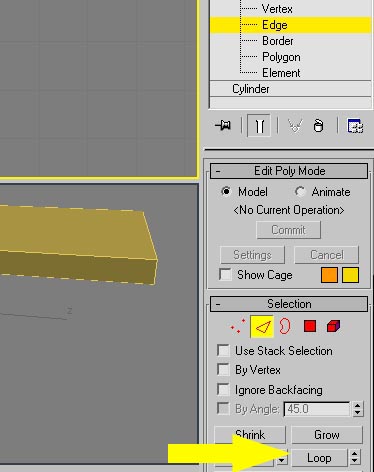
6.Adding details to the chair leg. Add EDIT POLY modifier to the chair leg from the modifier stack. Click the ‘plus’ symbol to expand the options and click EDGE. Now you can access the individual lines that make up the shape. In FRONT viewport, click one of the top HORIZONTAL lines on the leg. To select the rest of the lines around the circumference of the leg, click LOOP in the modify panel. Now, choose the SCALE tool (near move and rotate). Now, using the TOP viewport, scale your line selection to make the loop bigger. This adds some detail to the leg.
7.Select the MOVE tool, then HOLD shift and move the leg in the TOP viewport. Holding shift whilst moving duplicates the selected object. Repeat this 3 times to make all the chair legs.
8.Making the back of the chair. In FRONT viewport, create a BOX primitive. Adjust position and size accordingly, as in step 2. Experiment with ALIGN tool if you like. In modify panel, change segments to 3, 3, 1.
9.Add EDIT POLY modifier to the back of the chair. Go to VERTEX sub-object level and select the MIDDLE vertices in FRONT viewport. Then, with vertices selected choose CHAMFER tool (click little rectangle symbol to the right of the word chamfer to bring up the dialogue box). Tick OPEN and slide up the chamfer value until you get desired result

10.Chamfer can also be used in LINE sub object mode. Select one of the lines around the edge of the back of the chair and use chamfer again, notice how it rounds the edges to soften them.
11.Now, select the chair SEAT object again (the first one we made). Add EDIT POLY, go to LINE mode, and press CTRL+A to select all. Now, use chamfer to soften the edges.
12.Now, select POLYGON mode and select the top centre polygon (where the buttocks would go). Use BEVEL tool (near where chamfer was) -click the small rectangle to bring up the dialogue box, and enter a NEGATIVE height and outline amount.
13.Finished! You can carry on adding details if you like -use CONNECT and CUT to add in extra lines to work with. One last thing: select all your objects and GROUP them to nest them into one node. (keeps your scene uncluttered).
(c) John Hammond, burnt.toast@ntlworld.com


Latest Comments